Paper: Surface coatings and finite-element analysis of layered fretting contacts.
Authors: Nikas, G. K., Sayles, R. S.
Published
in: Proceedings of the Institution of Mechanical Engineers
(IMechE), Part J: Journal of Engineering Tribology, 2009, 223(2),
159-181
Abstract
A fundamental, two-dimensional finite-element analysis of a coated, flat surface in fretting contact with a flat-rounded punch is presented with detailed listing of all modelling steps. A large number of basic results from a parametric study has been derived, focusing on the stress analysis and the effect of coatings on the life expectancy of the coated solid, without actually getting into the ambiguities of life evaluation. Parameters included in the study are the metallic coating thickness (5, 20, and 50 µm) and elastic modulus, the endurance limit of the coated substrate and the normal and tangential loads applied. A summary of the stress-analysis results is presented in a figure with nine diagrams, which assists the quick selection of the optimum parameter values for maximising coating performance and minimising the risk of fatigue within the design limits used in the study. The model is realistic in that it does not use idealised load distributions in the fretting contact but actual geometrical solids of finite dimensions in contact under normal operating conditions, letting the finite-element analysis software resolve the loads and stresses, which are subsequently validated.
Some figures from this work
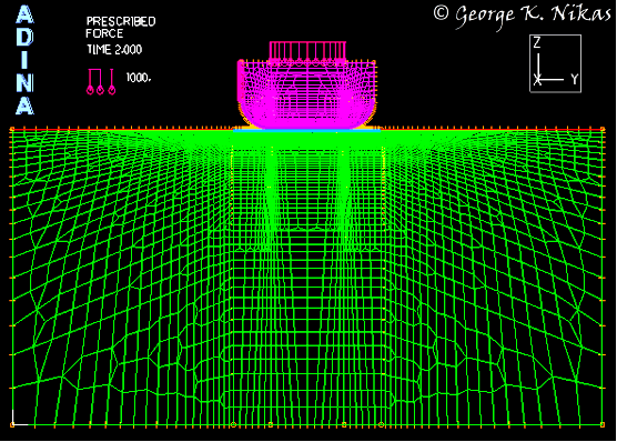
Figure 1(a) shows the finite-element mesh for the two-dimensional fretting contact of a flat-rounded punch on a coated substrate in plane strain. A normal load is applied on the upper surface of the punch, followed by a horizontal load exerted to the left side of the punch to simulate fretting conditions. The mesh is intelligently constructed to be dense in the areas of interest (such as at the highly-stressed contact edges) and coarse in areas where accuracy is of less importance, such that computational speed is not compromised. This model contains approximately 20,500 to 38,500 finite elements, depending on coating thickness, with the minimum element size in the coatings equal to approximately 1 µm near the two edges of the contact, which are the regions of stress concentration. Figure 1(b) shows the finite-element mesh at the right edge of the contact. The model was developed with the commercial software ADINA and was validated using established contact mechanics theories, showing excellent agreement, as detailed in the paper.

(a)

(b)
Fig. 1. (a) Finite-element mesh for the 2-d fretting contact of a flat-rounded punch on a coated substrate. (b) Detail of the mesh at the right edge of the contact (coating shown in red colour).
An example of the results in the paper is presented in Fig. 2. Figure 2 shows the effect of the substrate coating thickness and elastic modulus on the maximum effective (von Mises) stress for normal load P = 5000 N/m and horizontal load Q = 250 N/m (Q/P = 0.05), assuming that the Coulomb friction coefficient is equal to 0.2 in the central, stick region of the contact, and equal to 0.6 in the outer, slip regions of the contact.

Fig. 2. Effect of the substrate coating thickness and coatings elastic modulus on the maximum effective (von Mises) stress (see contour lines with labels in MPa) for P = 5000 N/m and Q = 250 N/m.
The paper contains a total of 63 performance diagrams. The results are summarized in a figure with nine diagrams, which facilitates the selection of the optimum parameter values for maximising coating performance and minimising the risk of contact fatigue within the design limits used in the study. This work has many applications, for example, turbine blade roots, spline couplings, bearing housings on rotating shafts, shrink fits and bolted parts, electrical contacts, etc.